The cascade controller is used for the absolute pressure of a VAV
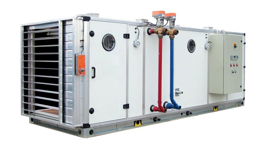
In recent years, variable volume air (VAV) systems have been widely used in air conditioning.
Systems can save energy while maintaining indoor comfort with variable frequency (VFD) drive technology
And building automation systems (BAS). Different from fixed air Volumetric systems in which the temperature of the supplied air is regulated due to the constant air flow to optimize control and energy consumption
VAV systems can regulate air temperature and air flow.
This control system has variable speed fans, mixing dampers, hot water heating coil and cold water cooling coil.
The most important functions are:
- Temperature control with (minimum and maximum limit)
- Fan pressure control
- Room air quality control
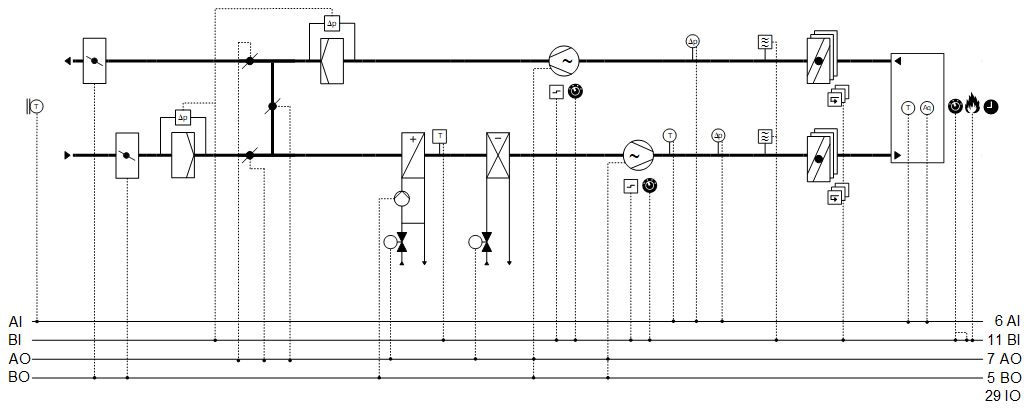
Functional diagrams / sequence diagrams
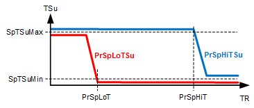
Cascading temperature control | ||
TSu SpTSuMax PrSpLoTSu PrSpHiTSu SpTSuMin PrSpLoT PrSpHiT TR | Inlet air temperature Maximum inlet air temperature set point Inlet air current temperature lower setting point High setting point of the inlet air current temperature Inlet air temperature setting point Low current temperature setting point High current setting point room temperature | |
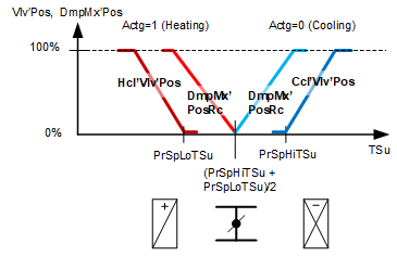
Inlet air temperature control | ||
Vlv-Pos DmpMx’Pos Actg=1 Actg=0 Hcl’Vlv’Pos Ccl’Vlv’Pos PrSpLoTSu PrSpHiTSu | Valve position Position of the mixed air damper Damper control to heat the mixed air Damper control to heat the mixed air Heating valve position Heating valve position Inlet air current temperature lower setting point High setting point of the inlet air current temperature | |
Seasonal temperature compensation | ||
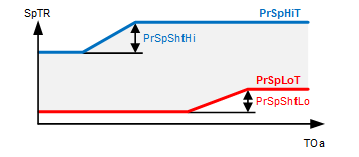
SpTR PrSpHiT PrSpShftHi PrSpLoT PrSpShftLo TOa | Room temperature setting High current setting point Change the current top point Low current temperature setting point Change the current low point Outdoor air temperature | |
Pressure control | ||
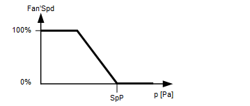
Fan’Spd SpP P | Fan speed Pressure adjustment point Pressure | |
Air quality control | ||
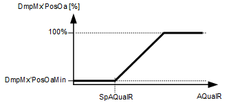
DmpMx’PosOa DmpMx’PosOaMin AQualR SpAQualR | Position of air mixer dampers for outside air Minimum position of air mixer dampers for outside air Room air quality Room air quality adjustment point | |
Description of functions
1- Waterfall temperature control (room / inlet air)
The adjustment point above and below calculates the inlet air at the outside temperature.
See the cascade control chart on the pages above
2- Basic settings for temperature control
Adjustment points for high and low room temperature
See Seasonal Temperature Compensation Performance Chart
3- Seasonal temperature compensation
The up and down adjustment point adjusts the room temperature based on the outside temperature
See Seasonal Temperature Compensation Performance Chart
4- Basic air quality settings
Settings for air quality
See Performance chart, basic air quality control settings.
5- Current operation mode
Current mode performance report: Off | Bright
6- The reason for the current situation
Report the reason for the current situation:
Exception | Function mode switch | Manual work mode | Scheduling | Performance change operation
7- Select the manual operation mode
Function status to: Automatic | Turns off or on
8- Cooling at night (free cooling)
If the conditions for cooling the room air outside the operating mode are on, it turns on the fans.
9- Common error (error indicators)
Display error in HMI or display pages